
 EN
EN
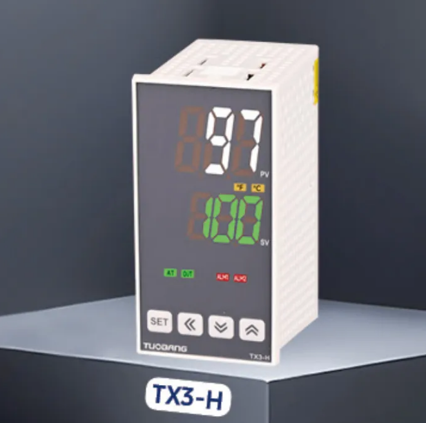
The Hidden Cost of an Uncalibrated Controller
Temperature controllers are the silent workhorses of industrial production. When they drift, the consequences are rarely immediate—which makes them dangerous. A controller reading 2°C low in a heat-treating furnace might not trigger an alarm, but it can quietly push an entire batch of aerospace components out of spec. The cost? Rework, scrap, or worse—field failures that surface months later.
Sensor drift isn't a matter of if but when. Thermocouples experience metallurgical changes from repeated thermal cycling. RTDs suffer resistance drift from wire stress, moisture ingress, or mechanical damage. Even premium sensors shift over time. The calibration question isn't about avoiding drift—it's about catching it before it compromises production.
A plastics extrusion plant in southern China learned this the hard way. The operation had been running a set of temperature controllers for eighteen months without verification. Production logs showed consistent temperatures, but finished product quality had been declining gradually—surface finish issues, dimensional instability, intermittent rejects. The maintenance team assumed the problem was raw material variation. It wasn't. When they finally ran a calibration check, every single controller was reading 3°C to 5°C higher than actual process temperature. The extruder was running cold for over a year. No single batch failed catastrophically, but cumulative scrap and rework costs over that period were substantial.
What Calibration Actually Means for a Temperature Controller
Calibration isn't just "checking if it's right." It's a systematic comparison between what the controller displays and what a reference standard says the temperature actually is. The reference standard must have known accuracy—typically traceable to national or international standards through an unbroken chain of comparisons.
The calibration process typically involves injecting certified thermocouple or RTD reference signals at multiple setpoints and recording the displayed temperature error at each point. A single-point check at ambient temperature isn't enough—processes rarely run at room temperature, and errors often vary across the measurement range.
Most industrial controllers support two types of user adjustments:
1.Offset adjustment — applies a fixed correction across the entire measurement range. Useful when the error is consistent. But if the error varies at different temperatures, offset alone won't fix it.
2.Span adjustment — adjusts the slope of the measurement curve. This corrects errors that grow or shrink as temperature changes.
A two-point calibration (low and high) is generally more reliable than a single-point offset, especially when the operating range spans more than a couple of hundred degrees.
The Standards That Define Acceptable Accuracy
IEC 60584 specifies tolerances for thermocouples. For a standard Type K thermocouple, the tolerance might be ±2.5°C at 1000°C—which means a controller could read 1002.5°C and still be "within spec" per the sensor's original factory tolerance. But that factory tolerance assumes the sensor is new and hasn't drifted.
For RTDs, IEC 60751 defines tolerance classes:
| Tolerance Class | Error at 0°C | Typical Application |
|---|---|---|
| Class AA | ±0.10°C | Laboratory / high-precision |
| Class A | ±0.15°C | Pharmaceutical / critical process |
| Class B | ±0.30°C | General industrial |
| Class C | ±0.60°C | HVAC / non-critical |
These are sensor tolerances, not controller tolerances. A controller adds its own measurement uncertainty—input circuitry, cold-junction compensation errors, and analog-to-digital conversion drift all contribute. The total system error is the sum of sensor drift, controller drift, and installation effects. Expecting better than ±1°C total system accuracy without regular verification is optimistic.
IEC 61298 provides the framework for testing process controllers, covering input accuracy, output linearity, and alarm verification. Following these standards isn't just about compliance—it's about having a defensible basis for quality decisions.
A Practical Step-by-Step Calibration Procedure
A solid calibration routine doesn't require expensive lab equipment for every check. Here's a practical approach that balances cost and confidence:
Step 1: Establish the reference. Use a calibrated reference thermometer or a signal simulator with known traceability. The reference should be at least four times more accurate than the controller being calibrated.
Step 2: Let everything stabilize. Temperature gradients matter. Place the sensor and reference in the same thermal environment and wait until readings settle—typically ten to fifteen minutes.
Step 3: Select calibration points. Choose at least three points: one near the lower end of the operating range, one near the middle, and one near the upper end. If the process runs in a narrow band, concentrate points within that band.
Step 4: Record as-found readings. At each setpoint, record what the controller displays versus what the reference indicates. Document the error. This "as-found" data is critical—it shows the drift trend over time.
Step 5: Apply corrections. If the controller permits offset or span adjustments, apply them based on the as-found errors. If the controller doesn't support user calibration, note the errors and apply correction factors manually in the control system or operator logs.
Step 6: Verify as-left readings. After adjustments, re-check all points to confirm the corrections worked. Record the new errors as "as-left" data.
How Often Should Calibration Happen?
There's no universal answer. Calibration frequency depends on several factors:
• Sensor type and quality — thermocouples drift faster than RTDs in high-temperature applications.
• Operating environment — vibration, thermal cycling, and chemical exposure accelerate drift.
• Process criticality — tighter tolerances demand more frequent verification.
• Historical drift rate — track calibration data over time to predict when a sensor will go out of tolerance.
A reasonable starting point for most industrial applications is annual calibration. But in harsh environments or critical processes, quarterly or even monthly checks may be justified. The key is to treat calibration frequency as a data-driven decision, not a calendar-driven one.
What Calibration Won't Fix
Calibration verifies accuracy—it doesn't improve a faulty installation. Common issues that calibration won't resolve:
• Incorrect sensor type selected in the controller configuration.
• Wrong wiring — thermocouples require the correct polarity and compensation cable.
• Poor sensor placement — measuring the wrong location in the process.
• Damaged sensor — a physically degraded thermocouple or RTD can't be calibrated back to health.
Calibration also doesn't compensate for response time issues. A slow sensor might read accurately at steady state but lag during temperature changes, causing control instability that looks like a tuning problem but isn't.
Building a Calibration Culture
The best calibration procedure is worthless if it isn't followed. Successful operations treat calibration as a continuous improvement discipline rather than a compliance chore. They track drift trends, analyze root causes when errors exceed limits, and use that intelligence to refine procurement specifications and maintenance intervals.
For facilities without in-house calibration capability, outsourcing to an accredited lab is a practical option. The lab should provide a calibration certificate with as-found and as-left data, traceable to national standards. But even with external calibration, in-situ verification between scheduled calibrations adds a layer of confidence.
Temperature controller calibration isn't glamorous work. But the difference between a process that runs reliably and one that produces scrap is often measured in single degrees—and a proper calibration program is what keeps those degrees honest.