
 EN
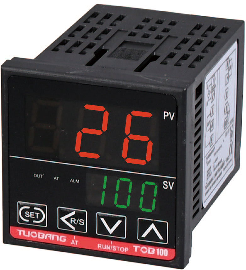
The controller output label matters more than the terminal number
A PID temperature controller and a solid state relay are often treated as a plug and play pair, but the first decision happens before any wire is cut. The output stage of the controller has to match the input requirement of the SSR. Most panel mount PID units ship with one of three output flavors: a relay contact, a DC voltage pulse sometimes labeled SSR drive, or a linear analog signal such as 4 to 20 mA. The relay contact version is the one that causes the most field confusion, because a mechanical contact closing and opening is not the same command as a logic level pulse, even though both eventually tell the heater to do something.
If the controller datasheet lists “SSR drive” or “voltage pulse” on the output terminals, the SSR input is a low voltage DC circuit, usually in the 5 to 24 VDC range. Polarity matters here. The positive terminal of the SSR input goes to the positive output terminal of the controller, and the return path completes the loop. Reversing that pair will not always destroy anything, but the SSR may stay permanently off or behave erratically. A quick multimeter check at the controller terminals, with the output forced to full demand, confirms whether the drive voltage is present before the SSR is connected.
The 4 to 20 mA case follows a different path. A current loop output cannot feed an SSR input directly. It needs a power controller or a driver board that converts the milliamp command into a firing signal the SSR can accept. Some integrators try to wire a 4 to 20 mA output across a standard DC input SSR and end up with a half-on state that never fully latches. The controller is doing exactly what it was configured to do. The mismatch sits in the interface.
The load side deserves the same attention as the signal side
Most wiring diagrams stop at the SSR input and leave the load side as a generic box. In practice, the load side is where the real engineering lives. The SSR is a switch in series with the heater, and the heater circuit has to be protected independently. A semiconductor fuse or a correctly rated circuit breaker upstream of the SSR is not optional. The fuse protects the SSR from a shorted heater element, and it also limits damage when the SSR itself fails in a shorted condition, which is a known failure mode for triac based AC units.
Zero cross SSRs are the usual choice for resistive heating loads driven by time proportioning PID outputs. The controller calculates a duty cycle, and the SSR switches full line voltage on and off across a fixed cycle time. Random fire or phase angle units exist, but they bring conducted emissions and harmonic considerations that are unnecessary for a simple resistive element. The wiring itself should keep the load conductors physically separated from the low voltage signal pair. Induced noise on the SSR drive line is a common reason a controller appears to lose its output or behaves as if the setpoint has shifted.
Heatsinking is part of the wiring decision, not a cosmetic afterthought. An SSR dissipates roughly one to one and a half watts per ampere of load current. A unit rated for a higher current without a heatsink may be fine at a fraction of its rating, but the terminal temperature is what matters. Bolting the SSR to a painted panel with no thermal compound is a wiring error disguised as a mounting choice.
A practical derating view for sizing the switch
Sizing an SSR for a resistive heater is not a straight nameplate match. The cold resistance of many heating elements sits below the hot resistance, so the first cycle after a cold start draws more current than the steady state value. Industrial guidance on heat tape and similar loads puts the first cycle inrush at roughly one and a half times the running current, with a further margin recommended for ambient temperature and enclosure conditions. A conservative selection table looks like this:
| Parameter | Typical field approach | Reason |
|---|---|---|
| Running current | Measured or calculated from heater rating | Baseline for all other factors |
| Cold start inrush | Roughly 1.3 to 1.6 times running current for many resistive elements | Element resistance is lower before warm up |
| Thermal derating | Additional margin, often around 2 to 2.5 times the running current for enclosed panels | SSR case temperature rises with ambient and load |
| Selected SSR rating | Above the derated figure, checked against the vendor thermal curve | Prevents junction temperature from running near the limit |
| Short circuit protection | Semiconductor fuse or coordinated breaker | Protects SSR and limits damage from a shorted element |
The exact numbers depend on the element and the enclosure, so the table is a starting point rather than a rule. What matters is the habit: measure the actual current, add margin for the first cycle, then check the thermal curve at the expected panel temperature. A unit that looks oversized on paper is often the correct size once the enclosure is warm.
Tuning and sensor placement change the wiring outcome
A correct wiring job can still produce poor control if the sensor and tuning are treated as separate tasks. The thermocouple or RTD should be placed where it sees the heater response the controller is supposed to manage. A sensor strapped to the outside of an oven wall reads the wall, not the air or the product inside. The PID then fights a process that is not the one being controlled.
Auto tuning is a reasonable first step on a new installation. The controller injects a step or a cycle and calculates proportional, integral, and derivative terms from the observed response. On slow thermal loads, auto tuning can take a long time, and the result may be conservative. Manual tuning remains useful when the load has a long dead time, such as a large oven with the element far from the sensor. Ziegler Nichols style rules give a starting point, but the final values usually need adjustment based on overshoot and settling behavior.
One detail that rarely appears in wiring guides: the SSR cycle time should be long enough for the heater and the process to respond, but short enough to avoid visible temperature ripple. A cycle time that is too short relative to the thermal mass causes the controller to chase noise. A cycle time that is too long produces swings that look like tuning problems but are actually a wiring configuration parameter.
When the SSR fails short, the wiring has to fail safe
Solid state relays fail in two directions. An open circuit stops the heater and produces a clear “no heat” symptom. A shorted output is the more dangerous case because the controller may show zero output while the heater receives full power. This is not a rare theoretical event. It is a recognized failure mode, and it is why an independent over temperature cutoff is part of a sound architecture. IEC 60730-2-9, the temperature sensing control standard, treats control failures and protective independence as part of the safety evaluation, not as an optional add on.
The practical wiring answer is a contactor or a manual disconnect in series with the SSR, driven by a separate over temperature instrument or a hardware interlock. The SSR handles the fast proportional switching. The contactor handles isolation and the abnormal condition. A current transformer on the load circuit can detect current when the controller commands zero output, which is a direct indicator of a shorted SSR. That signal can trip the upstream contactor without relying on the temperature controller itself.
In one retrofit at a chemical plant in southern China, the existing control panel used a PID controller and a zero cross SSR with no independent cutoff. A heater element failed and the SSR shorted in the same event. The panel showed a normal reading until the over temperature alarm on a separate legacy gauge finally caught the rise. The fix was not a different SSR. It was a contactor upstream, a current switch on one load leg, and a dedicated over temperature limit instrument wired to drop that contactor. The wiring diagram grew by a few terminals, and the failure mode changed from uncontrolled heating to a safe shutdown.
What a clean installation actually looks like
A clean PID to SSR installation has a few recognizable traits. The controller output type matches the SSR input, and the signal pair is twisted or shielded where the panel is noisy. The load conductors are sized for the heater current and protected by a fuse or breaker selected for the SSR’s short circuit behavior. The SSR sits on a heatsink with thermal compound, and the heatsink is mounted where convection can move air across the fins. The sensor is in the process, not on the panel. The tuning parameters reflect the actual thermal response, not a copied value from a similar machine.
Suosite builds temperature controllers and solid state relays as a matched product family, with in house production and testing across both sides of the control loop. For panel builders and OEMs sourcing both components from one place, the wiring compatibility question becomes a datasheet check rather than a field experiment. The company’s manufacturing base and inspection process support consistent terminal layouts and output configurations, which shortens the commissioning step when a new panel is powered up for the first time.
Table of Contents
- The controller output label matters more than the terminal number
- The load side deserves the same attention as the signal side
- A practical derating view for sizing the switch
- Tuning and sensor placement change the wiring outcome
- When the SSR fails short, the wiring has to fail safe
- What a clean installation actually looks like